ibjet
-
Posts
239 -
Joined
-
Last visited
-
Days Won
9
Recent Profile Visitors
2,978 profile views


-
Those retainer rings are $0.89/ea. at Pegasus Auto Racing supplies: https://www.pegasusautoracing.com/keywordsearch.asp?KeywordStart=Camloc+stud+retainer+ring&KeywordButton=Go Oh, wow, only $0.29 at Spruce, way cool. Those are a different configuration, mine are like my link shows and haven't had any come off. Nice that Camloc stuff is easy to find and not too pricey. Oops, now I see Spruce has the internal tooth version too.
-
I just bought some for my CTSW (not sure if the CTLS is the same). So, mine are Camloc 2600-4 Studs. I also bought one Receptacle, 212-12. I got the Studs from Aircraft Spruce (sometimes eBay has a good deal on multiples). I think I paid $2.20 ea for (10) and about $9 shipping . And the Receptacle I did get from eBay, it was $2.07 with $3.75 shipping. Oh, and there is a little spring retainer ring that I found at Pegasus Auto Racing Supplies. They showed a part number of 6071 with a description of Camloc 2600/2700 Standard Stud Retainer Ring. They were $0.79 ea. (got 10 to got with the Studs) and shipping was $8.99.


-
A few more pics of my progress (this is a story of the tortoise and the hare, ha ha)! My new Camloc receptacle bracket is finished (located in the airplane and marked, then put in all the holes), the new flanges/spacer inside my lower/left engine mount tube have been load tested to 600 lbs., and the flanges/spacer did not move. Now I need to put this project on the back burner, have a new mini split A/C to install. Excited about that too!


-
I bought just the duel gauges from Lockwood Aviation. When I figured out that you have to restrict the airflow volume to the gauges (with the little 90 degree on/off valves) then it worked fine and easy (before that the gauges were swinging wildly). I made a little bracket that I could clamp to the flange on my air cleaner box and that holds the gauges up where I can see them from inside the cockpit. I just took a picture of it in the box. Thought I had a picture of it all hooked up. I just looked on the Lockwood site and they do not show any hoses. Hmmm, I'd call I guess.

-
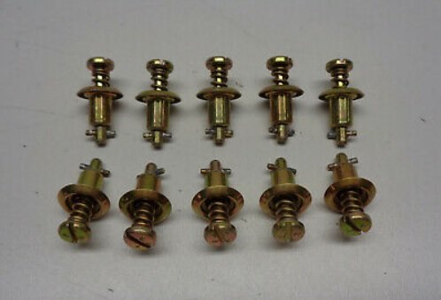
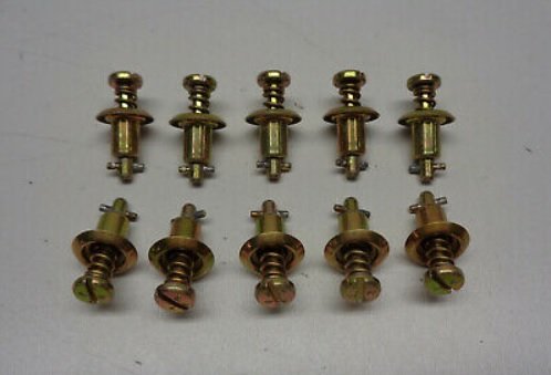
Thanks CT9000 and Tom. I have a dozen of those star washer/retainers on order. I removed it today by prying a skinny knife blade under the washer one place, then I slit it with my Dremel motor cut off wheel. Once I got that off, I realized the stud was still held on by the little cross bar. So, pleased to realize I did need to use the Camloc pliers after all! Tomorrow I'll put the 5 holes I need in that bracket and then the cleaning and painting phase is next. The engine mount has lots of chipped paint and even a little rust showing thru. I hope to make it look like new. I guess I'll buy a small can of white enamel primer and a spray can of Gloss white Rustoleum. Unfortunately, I realized that the Camloc studs I bought are one grip length too long! I got them quite reasonably, hope the same source will have the shorter ones.


-
I hit a little snag - I need to remove the Camloc stud where my new bracket will mate to the lower cowling. I have new studs but my old ones are held on by a specialty star washer (it's called a retaining ring) that gets forced over the barrel shaped carrier for the stud. The Camloc pliers that I bought are for some other kind of Camloc. QUESTION - Has anybody removed one of these? I will try to pry up the star washer on one side with a steak knife and then cut the star washer with a Dremel cut off wheel. I will put some grind marks on the steak knife, but that would be sacrificial, ha ha. I should have taken a picture of one of the camloc installations, forgot to. But I'll show the camloc studs and the star washer here so you can picture what I'm asking about . . .

-
A little progress (see pics) . . . Next I get to test fit up my engine mount and upper/lower engine cowling so I can finish position the bracket and match drill it to the engine mount frame and mark the center hole where the Camloc receptacle will go. Then I'll bring it home, and make the 3 holes needed for the receptacle. Then I will do that 600lb pull test of the new details inside the one engine mount tube. I already have a "fixture" for that (that I made to check and straighten the engine mount - I did straighten a little bend I had in the upper/left part of the engine mount). Then it will officially be time to clean up the engine mount and paint all the new steel parts and touch up paint the engine mount. I have not even opened my mini steam cleaner. I plan to use that on the whole engine. The video that came with it looks amazing. It's a very small "stream of steam" ha ha, but looks very strong too. It should be very helpful in cleaning the cooling fins of the radiator. Hmmm, I'll post a link to the Amazon page on that mini steam cleaner, if that sounds interesting view the video: https://www.amazon.com/gp/product/B07H8ZV4Y3/ref=ppx_yo_dt_b_asin_title_o09_s00?ie=UTF8&psc=1 I will use it mainly with the little spray wand, it's toward the end of the video.


-
The Mfr of my gauges (2006 CTSW) was UMA Instruments. There Ph# is 540-879-2040.Very reasonably priced and nice to work with.
-
I had my oil pressure reading go bonkers on me before, similarly to your experience. It turned out the be the gauge itself. Roger Lee advised at the time that the senders very rarely go out. I bought a new gauge from Aircraft Spruce, but found out the the original Mfr overhauls the oil pressure gauges and temperature gauges quite reasonably. My CT is a 2006, so not sure if the gauge story would be the same on yours. I will look up the company name and phone number that I have and get back to you right away.
-
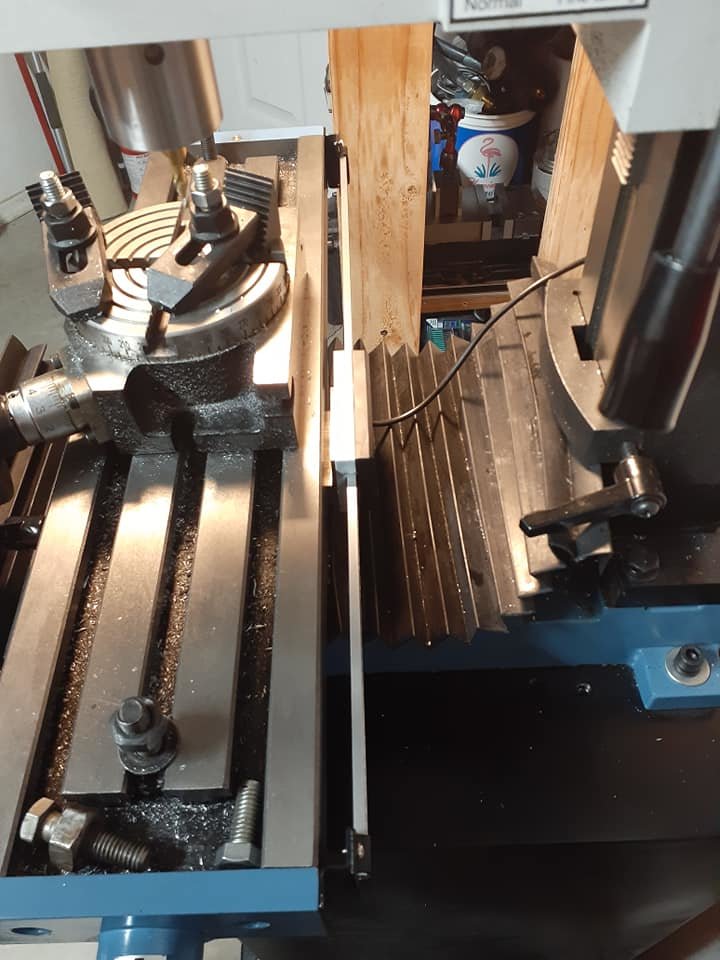
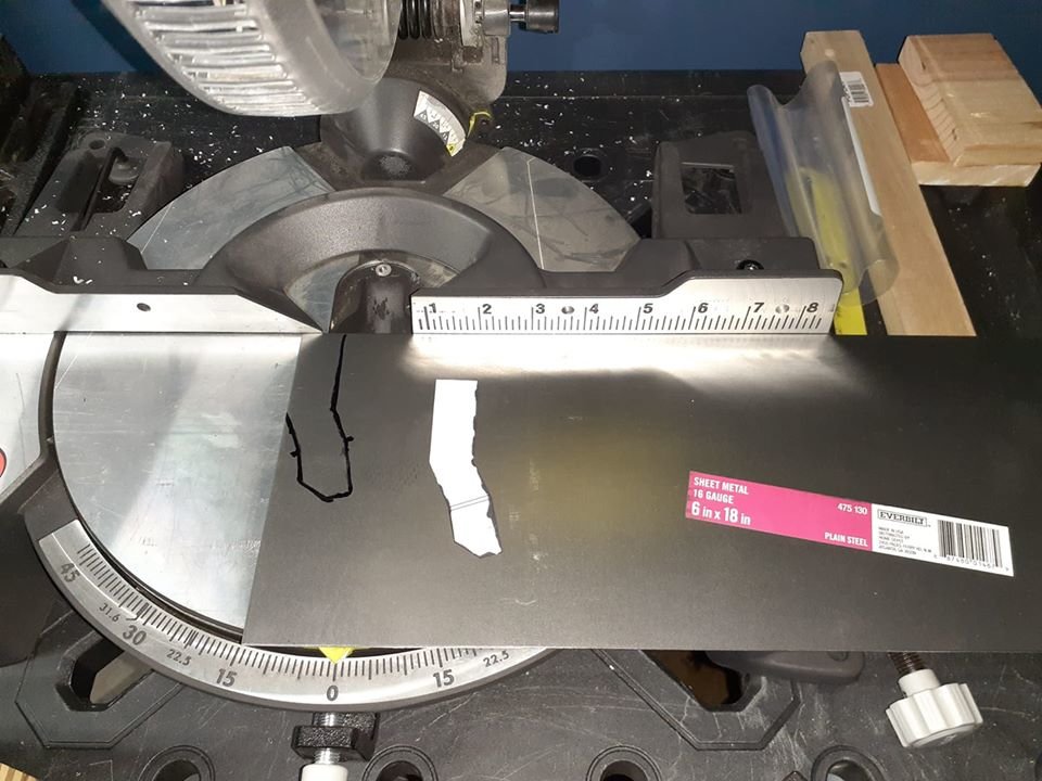
Sharing a few more pictures of my progress. First several show the cracked Camloc receptacle bracket. I will cut it off flush with the rectangular tube and rivet on a replacement which I'm working on today. I will leave it blank, clamp it in place, and test fit the engine mount and cowlings to finalize position and hole location (for the Camloc receptacle, which is cracked on one end). The last picture shows the crane scale that I just purchased to proof load the flanges/spacer inside the engine mount tube. This one is 600lb capacity, I wanted to get a higher capacity, but they were much more expensive and all had long delivery times. I'll have fun making the bracket, I'll clamp the strip of sheet steel on my rotary table so I can rotate to all the different angles that I will need to cut. The rotary table and the chop saw have been golden to me on this project!


-
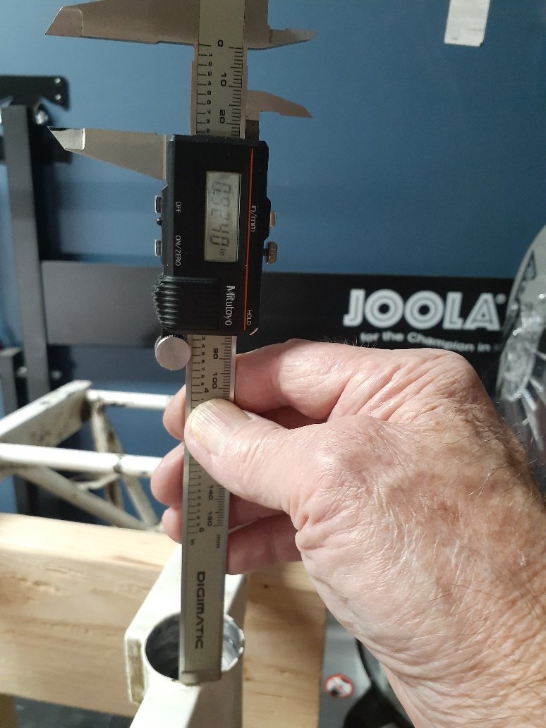
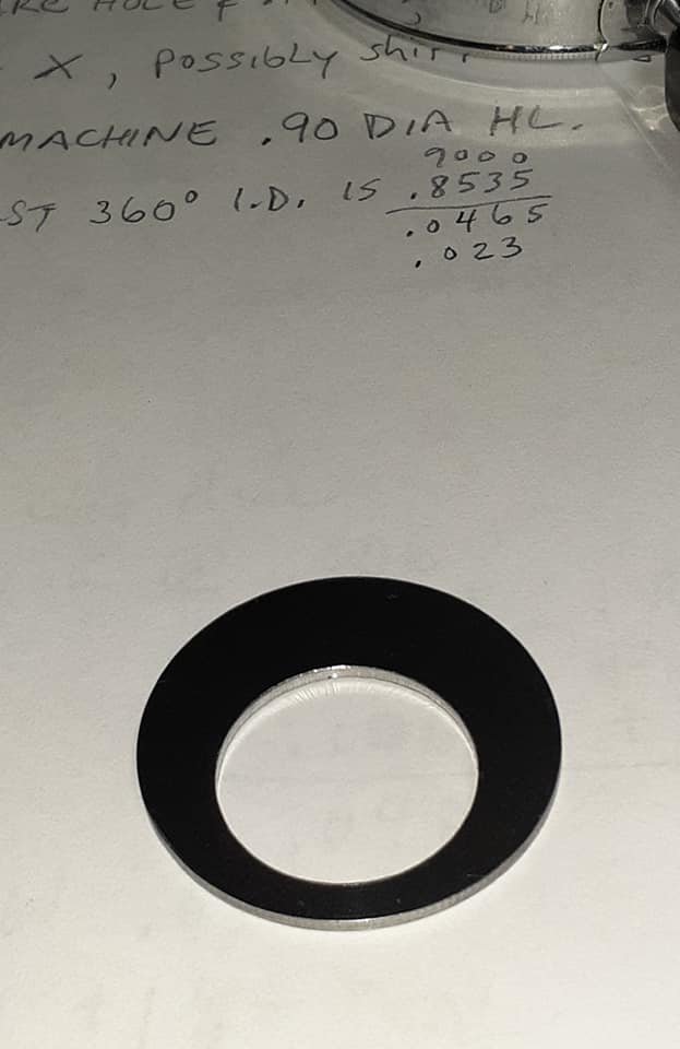
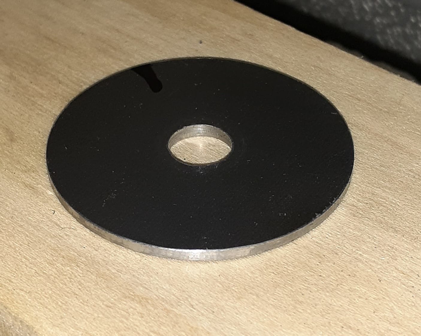
One more picture for now - I finished the offset hole in the second flange and installed them both yesterday. I added Loctite 620 before and after installing each one against the spacer (in between them). Measured the .91/.92 dimension (it was .9125) and clamped them in place while the Loctite cured. This picture is after I removed the clamp and cleaned off the excess Loctite. I was very pleased, once I slipped the flanges into place they would not move side to side at all, each one was custom slip fit. I have a broken tab on the lower most portion of the mount which I will remake and pop rivet on next. I was amazed that the part I need exists because it was done that way originally! I guess that one bolted on, I have to make mine a little longer and I'll attach it with blind rivets. I need to correct one dimension in my MRA, so I'll see if I can get by with adding this tab to my existing MRA. Mean while I'll draw it up and make it and order the rivets. And on and on it goes!

-
Thx okent, sent you a message
-
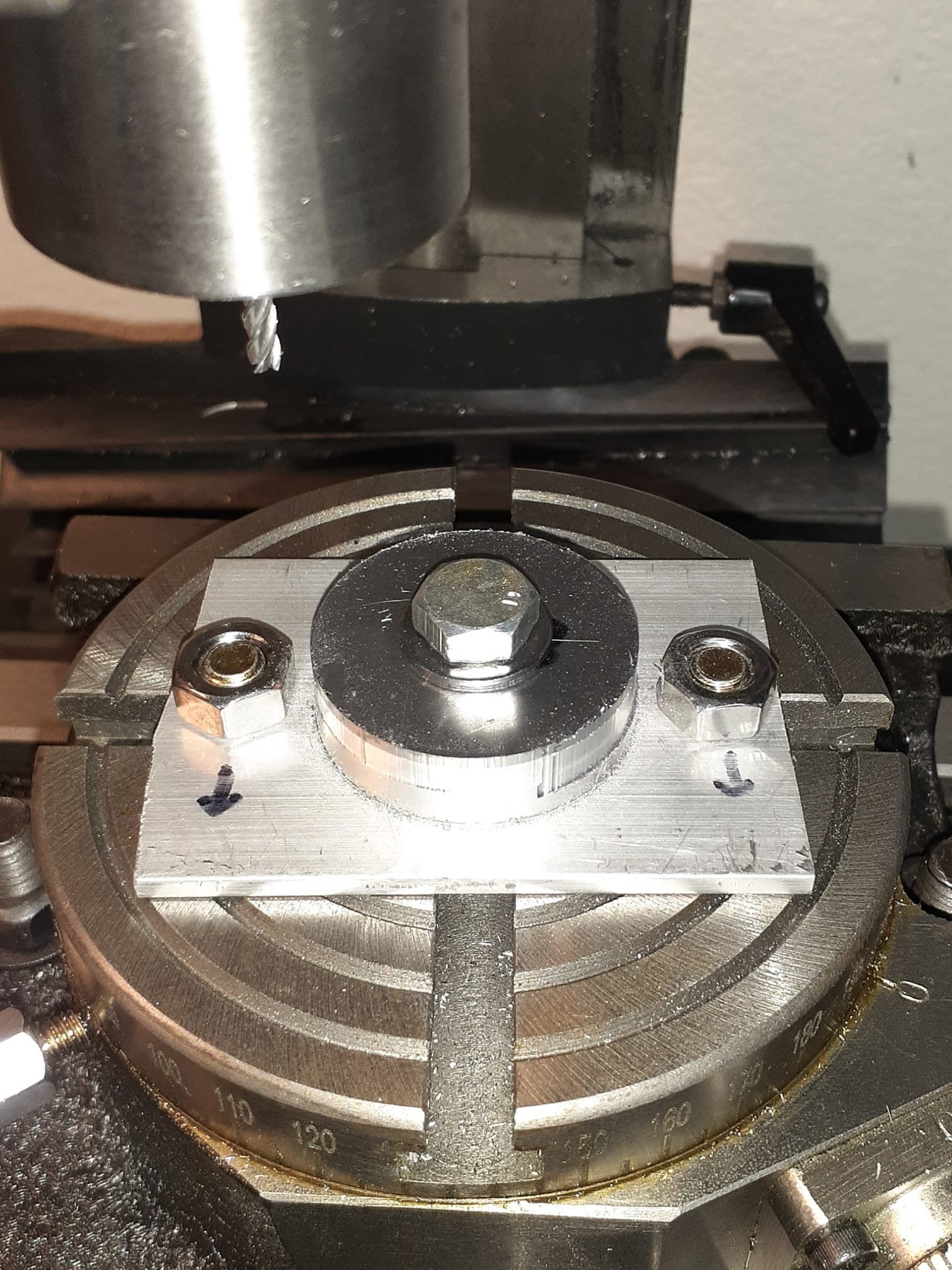
Last big hurdle was to machine the offset hole in the flanges that go in the engine mount tube. Still have to machine the hole in the second one, but I saved my set up by placing two clamps against the first part to serve as stops. Along the way I decided I had to install my digital read out to keep track of where the centerline of the rotary table was in relation to the spindle. Tomorrow I'll finish the second flange and Loctite them into the engine mount, yay!


-
Adding a few more shots of my progress. I milled the first of the 2 Flanges tonight. It didn't quite fit in the engine mount tube, so I mounted it on a little arbor and in a drill motor which I placed in a vise. Then I filed the OD until it just would slip into the tube. I wanted a tight fit so the Loctite 620 would cure properly.


-
Wow, great info Tom, thanks! I have thought a lot about the mis-alignment in my engine mount. I'm thinking that there must have been several engine mounts that were fabricated with the same error (because weldments like that are made in batches). There likely was an order of say 20 to 40 weldments that were done in the same lot as mine. It's very disconcerting that Flight Design would have accepted them that way. Those mounts are pretty amazing in most respects. Anyway, I'll show you where my engine mount was bent (I straightened it, but you can see the chipped paint. You can see that this is a weak point of the weldment. Thanks, really appreciate the detail info.